but not the same as, as the keyboard I had.
What’s old is new again! https://hackaday.com/2019/11/18/optical-keyboards-have-us-examining-typing-at-light-speed-ish/
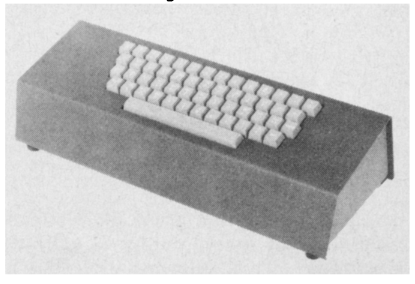
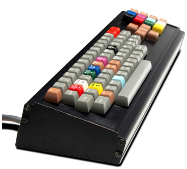
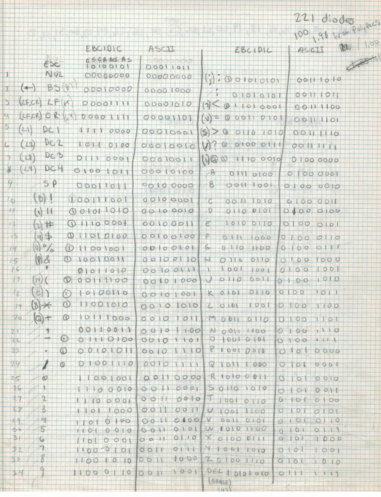
40 years ago, I was given an old keyboard from my high school teacher, the SP-251 (don’t know the vendor). It was optical. There was a anodized black metal plate inside the keyboard with 13 channels running left to right. The left side of each channel had a small incandescent bulb. The right side had a CdS photo cell at the end of each channel. Along the top was a metal rod which held the top end of the metal bars attached to each key. Each of these bars ran top to bottom with a spring to keep them up out of the channels. Each key had a different combination of tabs that protruded downward, so that when a key was pressed, the tabs broke some of the beams, encoding the value of the key. Strangely, the bit coding of these tabs was not ASCII nor the older EBCDIC, as far as I was able to tell at the time. In hind sight, it clearly is not.
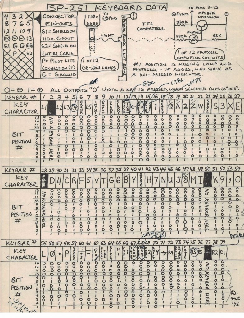
in 1975 by reverse engineering it. Perhaps they were a previous owner?
I wanted to use this keyboard with my hand-built wire-wrapped RCA COSMAC 1802 microcomputer, and I knew that ASCII was what I wanted, so I literally broke off tabs that were incorrect and soldered on tabs that were missing, changing the encoding to ASCII. At the time, I had no access to a ROM to encode the conversion or an ability to program one, which was clearly the better solution to convert the key codes in hardware. I did consider building a discrete diode implementation of a ROM, but estimated at the time needing 221 diodes, which would have been a lot of work to wire up. And, I didn’t want to convert the keys in software, as at the time every byte of machine code had to be hand-keyed in in binary. I wanted to make the need to use the 8 binary toggle switches unnecessary when entering the bootstrap, not make myself do it in order to use the keyboard.
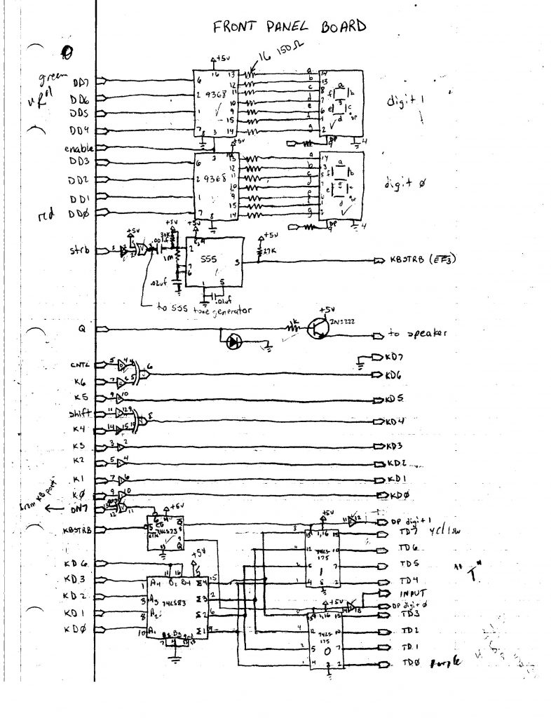
After doing that, I built a simple digital circuit that would convert pairs of key presses into the equivalent hexadecimal (if the user was careful to press only 0-9 and A-F); this allowed me to much more rapidly enter the bootstrap code when turning on the machine.
I did this using a 74LS83, which is a 4 bit full adder. If KD6 is 0, which is the case for keys 0-9, 0 is added to 0-9, so the least significant nibble of their ASCII codes is propagated unchanged (‘0’ = 0x30, ‘9’ = 0x39). But if KD6 is 1, which occurs for upper case or lower case A-F keys, but not if CNTL is pressed, then the value 9 is added to the lease significant nibble of their ASCII codes, resulting in the correct values (‘A’ = 0x41, ‘F’ = 0x46; 1 + 9 = 0xA, 6 + 9 = 0xF). The upper and lower nibbles are alternately latched using the Q and /Q outputs of a JK flip flop. Not shown is the source of ON7, which controls when we are in this hex input mode vs. normal key data mode.
I wish I still had that keyboard, but it was damned heavy and after a bunch of moves when I was young I ditched it. I think somewhere I have a photo; if I dig it up I’ll post it.
Related links:
http://www.nelson-miller.com/overview-optical-keyboard-technology/
http://www.oldcomputers.net/compucolor-8001.html
https://ieeexplore.ieee.org/stamp/stamp.jsp?arnumber=6323540