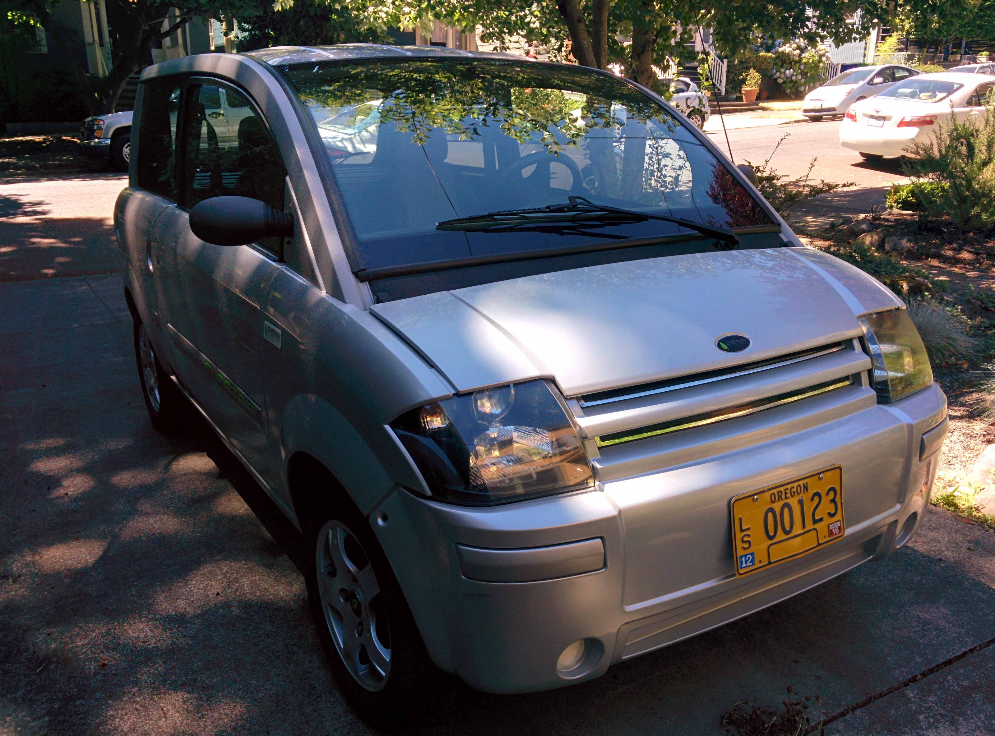
I used to have a 2007 Zenn NEV (neighborhood electric vehicle) by Feel Good Cars / ZENN Motor Company. This small car was one of the very first mass-produced electric vehicles available in the US, that was not truly a suped-up golf cart. However, having shipped in low volumes and eventually going out of business, the car is not without some major flaws. One of the most common to fail, and expensive to repair, is the speedometer / odometer / battery level display, what Zenn calls the Instrument Cluster. When mine started to fail, it at first seemed to be related to moisture. My car has another common flaw, a leaky roof due to a failure of the glue that holds down the roof panel. After using a dehumidifier to dry out the car, I noticed the display started working again. However, this cure did not last for long, and later attempts to fix the display failures did not succeed.
Come the fall of 2014, I decided to finally sell the car. But what to do? The display didn’t work, and a new one would be $800. I had considered trying to take the module out of the car to troubleshoot it in the past, but it was clear it was a major undertaking. First, one was instructed in the service manual to remove the dash. Yikes! So that held me back for a bit. Eventually I decided to go for it. It turns out, one does not need to completely remove the dash. I did the following to remove the module (this goes with the instructions on pages 32-33 of the service manual):
- did not remove the steering wheel (really did not want to do that!)
- removed the side view mirrors, as the panels inside the pillars block the dash board from being lifted away
- removed the panel where the heating controls are, but I don’t think this was necessary
- did not disconnect the speakers (the instructions say to remove them, but since I was trying to keep it simple and not remove the whole dash, I left them in)
- removed the lower black plastic retaining rivet from the instrument panel (the lower part, by the light)
- removed the 2 left and right black plastic retaining rivets from the instrument panel
- removed the 2 left and right square head screws below the HVAC vents
- did not disconnect the heating throttle switch on the housing diffuser (looked difficult and unnecessary)
- removed the screws that hold the instrument cluster in
- started pulling the dashboard loose, just enough on the passenger side to get the instrument cluster out (I had to disconnect the passenger side fan duct)
- (the hard part)reached in through the hole in the dash where the instrument cluster mounts, around the back side of the now-loose instrument cluster, and disconnected the two cables
- pulled out the instrument cluster through the hole (by loosening the dash board, there is enough room to maneuver the instrument cluster to get it out)

Next, I took the cluster to my workbench, and inspected the circuit board very thoroughly. Nothing appeared the slightest bit burned or damaged; none of the components or copper traces were dark, warped, or scorched. Time to power it up.
Using the wiring diagrams in the service manual, I figured out how. I luckily had on hand a number of unused pins for similar Molex-style connectors, and stuck 4 in the proper holes in connector J4. In the photo below, you can see I wrote with a sharpie the pin numbers on the end with pins 22 and 11. Pin 22 needs to be connected to ground, while pins 9, 10, and 11 need to be powered with +12volts DC. I connected 9, 10, and 11 together with solder, but wire would work just as well.

The display now powered up, but, as expected, had random segments dark while others were powered. It’s hard to make out the speed or distance if all of them are not on when they are supposed to be! Poking around at the board, I discovered the flex cable that connects the display panel to the circuit board was the culprit. Pressing it down against the glass caused some of the segments to come on. Pressing down the whole width of the cable against the glass made the whole display appear to be correct.
Unfortunately, such a flex cable connection is hard to repair. They are somehow soldered and glued at the factory, but not something I felt comfortable fixing. I did try adding a bit of glue between the cable and the glass, but this was ineffective.
I decided the solution was to make a clamp out of brass that could just stay there forever, keeping pressure on the flex cable. I put some tape between the brass and the flex cable so it didn’t damage the cable. I used a strip of brass from the hardware store that was as wide as the flex cable, and cut and bent it to reach around the side of the instrument cluster and press against the circuit board connector on the opposite side. It’s kind of a squared-off U shape.

Brass clamp holding flex cable against the glass display
Here’s a close up of the side pressing against the glass. Unfortunately I didn’t take any pictures of what’s underneath — the flex cable glued to the glass.

Here’s the other side, where the clamp grabs on. It’s important to shape the brass such that it cannot possibly short out the flex cable connector pins.

Here’s another view.

Another view
Here’s proof the repair worked. When you first power up the cluster, it tests the display by turning on all segments. I captured this photo, showing all the critical segments are now lit. There might be a couple on the lower left number that are still not fixed, but I’m not even sure what that section of the display is for.

After a second or two, the normal display appears.

A nice aspect of this repair is that, once the back cover is screwed on the instrument cluster, it just touches the brass clamp, ensuring it can’t come loose.

All that was left at this point was mounting it back in the dash and reassembling everything.
The hardest part of this was reaching in the hole on the dash and getting the cables reconnected. Reattaching the passenger side HVAC vent was also a bit difficult, but doable.

Nice to have the display working again. Too bad I got too busy at work after I did this repair in November to sell the car… hopefully I will do so soon.